Understanding ISO 2768 Standard
In Brief
- Simplification: A standard that lightens drawings via general tolerances rather than detailed ones everywhere.
- Structure: Two parts, ISO 2768-1 (linear/angular) and ISO 2768-2 (geometric).
- Classes: f, m, c, v (1) and H, K, L (2) define precision.
- Benefit: Better communication, robust quality control, cost reduction.
- Exceptions: Critical functions always require a specific tolerance.
Origins and Objectives
The ISO 2768 standard was developed to address a recurring problem: on a drawing, not all dimensions can be over-toleranced without cluttering the reading. The objective is to propose standardized general tolerances, applied by default where no specific requirement is indicated.
This logic is crucial in multipolar production. A client in Europe can have the same part produced in Asia, while maintaining a consistent interpretation.
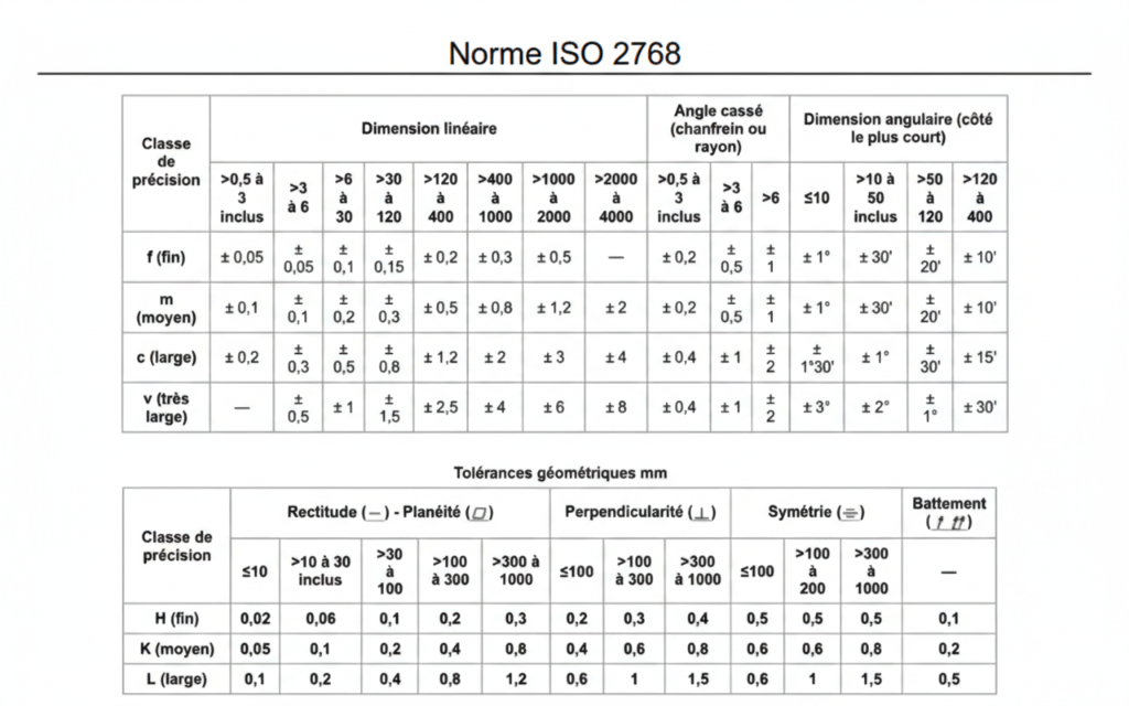
Official ISO 2768 Tables
General tolerances for linear, angular, and geometric dimensions.
The Two Parts of the Standard
-
📏
ISO 2768-1 (Designation e.g.: ISO 2768-m)
Concerns linear tolerances (lengths, diameters, distances) and angular ones. The class (f, m, c, v) defines fineress. A medium class (m) is suitable for most standard parts.
-
📐
ISO 2768-2 (Designation e.g.: ISO 2768-K)
Concerns geometric tolerances: straightness, flatness, perpendicularity, symmetry, run-out. Classes H, K, L. Essential to ensure assembly without specifying everything.
Value Added in Industry
In a world where deadlines compress, tolerance is an economic lever:
- Too tight: Exploding costs and unnecessary scrap.
- Too loose: Assembly and reliability problems.
- ISO 2768 (The Middle Way): Fewer back-and-forths, targeted controls, and reproducible quality.
Application Areas
CNC Machining & General Mech
Serves as a base for chassis, housings, tooling. Avoids cluttering control programs for secondary dimensions.
Aerospace & Automotive
Used for non-critical elements or environment parts, allowing quality effort to focus on safety zones.
⚠️ Mind the Exceptions
ISO 2768 does not replace functional analysis. As soon as a dimension conditions a fit (bearing), a seal, or safety, a specific tolerance must be explicit on the drawing.